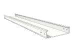
cable tray
Formed via integrated stamping; ensures balanced heat dissipation and temperature control; features drainage holes to prevent water accumulation and resist moisture-induced corrosion.
 [language-switcher]

 August 31, 2026
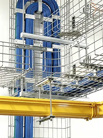
Correct cable tray installation provides a stable, accessible route for power, control, communication and data cables. A successful installation requires more than mounting brackets and joining tray sections. The contractor must also verify cable loads, support spacing, routing clearances, fitting locations, corrosion protection, grounding requirements and future expansion capacity.
Cable tray configurations and installation requirements vary by project, product type and local regulation. The approved drawings, product data and applicable electrical and structural requirements must therefore take priority over any general installation guide.
Shandong Hongfeng Power Technology Co., Ltd. manufactures cable trays in different structures, specifications, materials and surface finishes. Its production facilities support straight tray sections, bends, tees, crosses, covers, connectors and other accessories required to build a coordinated cable-routing system.
Installation should begin only after the cable tray layout and supporting structure have been reviewed.
The installation team should confirm:
If the tray system is customized, verify that the supplied straight sections and accessories correspond to the approved drawing before work begins.
Different cable tray types require different handling and installation methods.
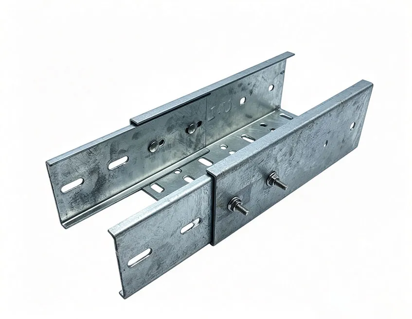
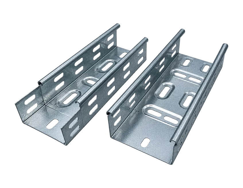
A ladder cable tray uses side rails and rungs and is commonly selected for larger power cables or cable bundles requiring open ventilation. A perforated cable tray provides more continuous bottom support for smaller power, control or communication cables. Trough-type trays provide a more enclosed route, while wire mesh trays offer flexible routing for selected lighter cable systems.
Do not mix components from different tray systems unless their dimensions, profiles, connection methods and materials have been confirmed as compatible.
Calculate the total weight of the cables planned for each tray route. The calculation should include:
A wider cable tray provides more routing space, but it does not automatically provide greater load capacity. Tray profile, material thickness, side-rail height and support spacing must also be considered.
Compare the approved tray route with actual site conditions. Check for conflicts with:
Any route change should be approved before installation rather than improvised after supports have been fixed.
The tools required depend on the supporting structure and tray material. A typical installation may require:
If a tray must be cut on site, the exposed edge should be deburred and treated according to the material and coating requirements. Unprotected field cuts can reduce corrosion resistance and damage cables during pulling.
Use the approved drawing to mark the tray centerline, installation elevation and support locations.
The marked route should:
Use a laser level or other appropriate equipment to keep long routes aligned. Misalignment at the marking stage can create connection problems and uneven cable loading later.
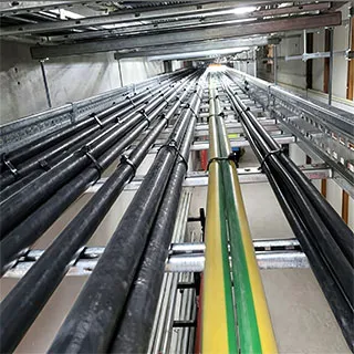
Supports transfer the combined weight of the tray and cables to the building structure. They must be suitable for the substrate, tray width, load and installation environment.
Common support methods include:
The attachment method must be compatible with concrete, masonry, structural steel or the relevant supporting surface.
Do not attach supports to non-structural ceilings, unsuitable wall finishes or other services unless the approved design specifically permits it.
There is no universal support interval for every cable tray.
The correct spacing depends on:
Supports are also commonly required near bends, tees, crosses, reducers, risers and other areas where load or direction changes occur. Their exact locations should follow the approved design and manufacturer’s recommendations.
Install anchors, brackets, threaded rods or structural clamps at the marked locations.
Before placing the tray, check that the supports are:
Loose or misaligned supports should be corrected before the tray sections are installed.
Begin from a defined reference point, such as a wall penetration, equipment connection or major direction change.
Position the first straight section on the supports and check its elevation and alignment. Secure it using the compatible hold-down clamps or fasteners, but avoid fully tightening every component until adjacent sections have been positioned and checked.
Continue adding sections in the direction shown on the layout drawing.
The side rails or tray edges should form a continuous, even route. Misalignment may:
Interfere with connectors
Create sharp cable-contact points
Place uneven stress on the tray
Complicate cover installation
Affect the finished appearance
Use the correct connectors rather than forcing misaligned tray sections together.
Fasteners should be tightened according to the approved installation method.
Over-tightening can deform thin sections, damage coatings or affect slotted connections. Under-tightening may allow movement or reduce the stability of the joint.
Where a specified torque is provided, use a suitable torque wrench.
Shandong Hongfeng Power Technology Co., Ltd. is a cable tray manufacturer located in Liaocheng, Shandong Province.
Its documented manufacturing resources include:
The company can support straight cable tray sections, elbows, accessories and customized project configurations.
Hongfeng applies quality control from raw-material procurement and manufacturing through final-product inspection. Its submitted qualifications include CE, IEC 61537 and ISO 9001 certification, as well as multiple product patents. The applicable certificate and product scope should be confirmed for each project.
Standard products are documented with an approximate delivery period of 3–5 days, while customized products are documented with an approximate production period of 7–15 days. In-stock accessories may be available for same-day shipment. Actual schedules depend on specification, order quantity, surface treatment and current production planning.
There is no single spacing suitable for every tray. Support spacing depends on the tray type, dimensions, material thickness, cable load, fitting locations and allowable deflection. Use the approved design and model-specific load information.
Grounding and bonding requirements depend on the electrical design and applicable regulations. Where required, continuity must be maintained across tray sections and fittings using approved connection methods.
Yes. Cable trays can be installed vertically when the tray, supports and cable restraints are designed for that orientation. Cables normally require suitable fixing to prevent their weight from being transferred improperly.
They can be cut when permitted by the installation procedure. Cut edges must be deburred, and damaged protective finishes should be repaired using a compatible treatment.
Support positions near elbows, tees, crosses and reducers should follow the approved design or manufacturer’s guidance. Fittings should not be left unsupported where their weight or cable load could deform the system.
We will reply you within 24 hours. If for urgent case, please add WhatsApp/WeChat:+86 188 6519 8768, Or call +86 188 6519 8768 directly.
We respect your confidentiality and all information are protected.
We will only use your information to respond to your inquiry and will never send unsolicited emails or promotional messages.
 Inquiry